(Additional contributors, alphabetically: Laz Kopits, Ryan Leong, Sheel Taskar, Daryl Yang, William Zang)
Building robust robotic manipulation policies requires diverse, high-quality demonstration data at scale. The challenge lies not just in collecting data, but in doing so reliably across multiple devices while maintaining temporal synchronization and handling the inevitable network disruptions of real-world deployments. This post details the system architecture behind the SF Fold dataset, a large-scale robotics manipulation dataset collected using UMI-style grippers.
Our Goal: Take the UMI concept from research prototype to production-ready hardware: a device anyone can pick up and use without specialized expertise, seamlessly integrated into cloud-based post-processing pipelines for scalable data collection.
Hardware Setup
The data collection system builds on the UMI (Universal Manipulation Interface) approach, using UMI-style still grippers equipped with OAK-D Wide cameras for 6-DoF pose tracking via ORB-SLAM3 in stereo mode. The setup supports bimanual manipulation tasks through a multi-puppet configuration: Left Puppet, Right Puppet, and Ego Puppet. Throughout this document, we refer to the data collection devices as “puppets”.
| Component | Specification |
|---|---|
| Gripper | UMI-Style Still Gripper |
| Camera | OAK-D Wide |
| IMU/Hall Sensors | 200Hz sampling rate |
| Camera Frame Rate | 30Hz |
| Control Interface | Physical button + LED feedback |
Button Controls: Long press creates/closes datasets, short press starts recording episodes. Color-coded LEDs display current system status.
OAK-D Wide Camera
The OAK-D Wide provides stereo vision for 6-DoF pose tracking using ORB-SLAM3. The camera is mounted pointing upward on each gripper to avoid occlusions during manipulation tasks.
Interactive 3D model of the OAK-D Wide camera. Click and drag to rotate, scroll to zoom.
System Architecture
The system follows a distributed architecture where multiple puppets coordinate through a central MQTT broker running on the Ego Puppet. This enables synchronized multi-view data collection while maintaining robustness against network failures.
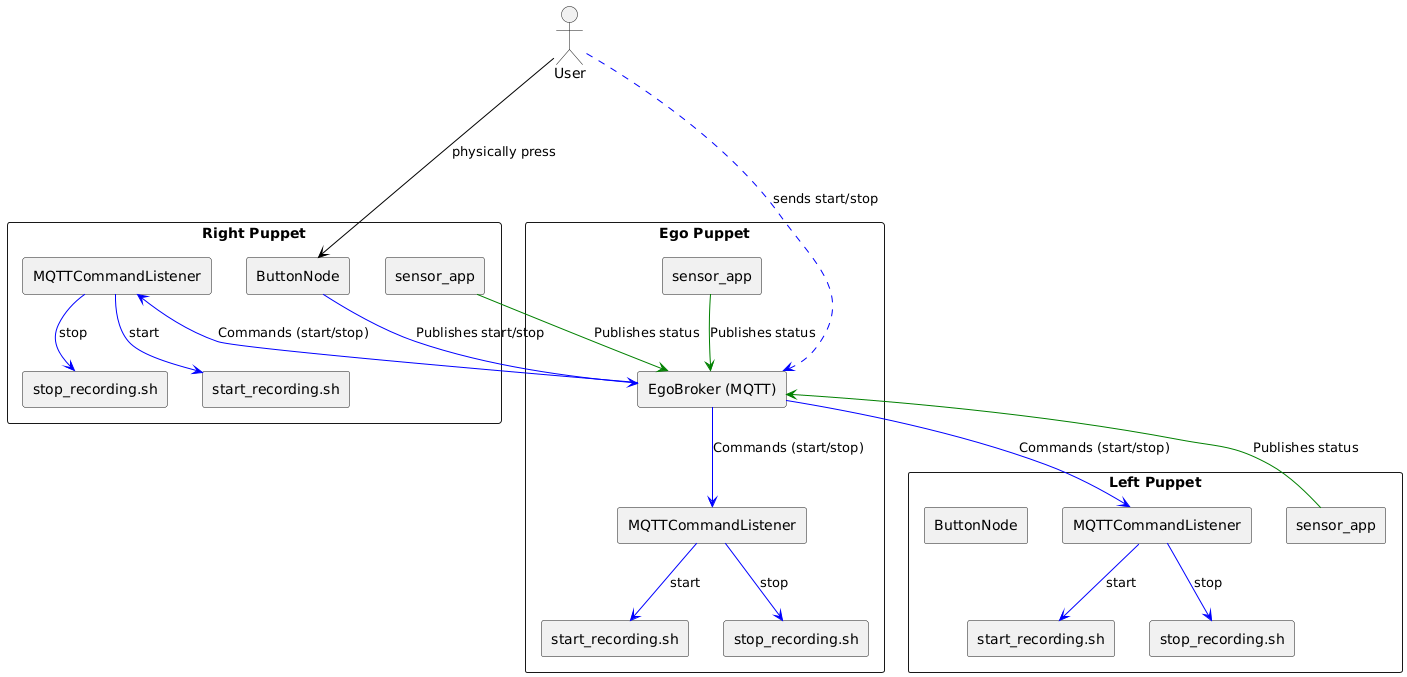
Architecture showing Right, Ego, and Left Puppets communicating via the central EgoBroker. Components include MQTTCommandListener, ButtonNode, and sensor_app. (Click to enlarge)
Puppet Communication
Puppet interaction follows a state machine: ON → DATASET_ACTIVE → RECORDING → UPLOADING
Each puppet runs three core components:
- MQTTCommandListener: Receives start/stop commands, triggers local recording scripts
- ButtonNode: Handles physical button input on Right Puppet, broadcasts commands
- sensor_app: Publishes sensor data and system status
When a user presses the button on the Right Puppet, the ButtonNode publishes to the Ego Broker, which distributes synchronized commands to all puppets, ensuring simultaneous state transitions and episode alignment.
MQTT Broker Setup
The system implements a dual-broker architecture balancing reliability with discovery:
| Broker | Port | Purpose |
|---|---|---|
| Cloud (GCS) | 1883 | Discovery only |
| Local (Mosquitto) | 1884 | All internal communications |
Key Design: The cloud broker serves only as a discovery mechanism. All data recording and episode management happens through the local broker, allowing fully offline operation after initial setup.
Cloud Broker Details
- Runs on Google Cloud infrastructure
- Each puppet publishes system metrics to
<GROUP_NAME>/<PUPPET_SIDE>/system_metrics - Metrics include broker status and IP address
- New puppets subscribe to discover their local broker IP
- Connection uses standard port 1883 with admin credentials
- Automatic fallback to searching mode if connection fails
Local Broker Details
- Mosquitto MQTT broker instance
- Handles all internal communications:
- Message routing between system components
- Episode transitions and sensor data
- State change notifications
- Maintains message order and delivery during disconnections
- Functions independently of internet connectivity
- All system events pass through this broker
Data Collection Flow
The data flow spans from physical demonstration through cloud storage, with multiple checkpoints for reliability.
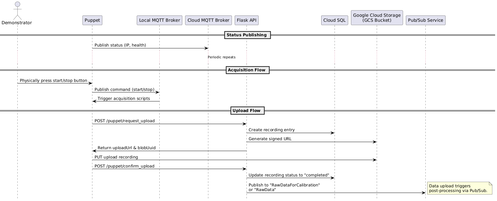
Complete data flow between Demonstrator, Puppet, MQTT Brokers, Flask API, Cloud SQL, GCS, and Pub/Sub. (Click to enlarge)
Status Publishing
Each puppet continuously publishes status (IP, health metrics) to the Cloud MQTT Broker, enabling system monitoring and discovery.
Acquisition Flow
When the demonstrator presses the start/stop button:
- Button press publishes command to local MQTT broker
- Command triggers acquisition scripts on all connected puppets
- Each puppet records sensor data with precise timestamps
Upload Mechanism
After recording completes, uploads follow a secure, verifiable sequence:
| Step | Endpoint | Action |
|---|---|---|
| 1 | POST /puppet/request_upload | Request upload, log to Cloud SQL |
| 2 | - | Flask API generates signed URL |
| 3 | PUT to GCS | Upload recording with signed URL |
| 4 | POST /puppet/confirm_upload | Confirm completion in Cloud SQL |
| 5 | Pub/Sub | Trigger post-processing pipeline |
Upload Flow Details
Request Upload: Puppet initiates via
POST /puppet/request_uploadto Flask API, which logs “Upload Requested” in Cloud SQLSigned URL Generation: Flask API generates a signed URL with time-limited write access to the GCS bucket
Data Upload: Puppet uploads directly to GCS using
PUTwith the signed URLConfirm Upload: Puppet confirms via
POST /puppet/confirm_upload, updating Cloud SQL to “Upload Confirmed”Trigger Processing: Completion publishes to Pub/Sub topics (
RawDataForCalibrationorRawData) for downstream pipelines
This mechanism ensures data integrity through explicit confirmation steps and enables tracking through Cloud SQL status entries.
Reliability and Synchronization
Collecting synchronized multi-view data across distributed devices requires robust handling of network failures.
Reconnection Mechanism
TCP connections can become stale without detection, causing silent disconnections. The system employs two mechanisms:
| Mechanism | Function |
|---|---|
| TCP Keepalive | Periodic health checks, detects broken connections even when idle |
| Socket Timeouts | 5-second max wait, prevents indefinite hangs |
Failure Behavior: When connections fail, puppets continue recording locally while tracking disconnection events. LED shows
CONNECTING_TO_BROKER(pulsing white) during recovery.
TCP Keepalive Details
- Activates periodic connection health checks
- Automatically sends small test messages when connection is idle
- Detects broken connections even when no data is being sent
- Configured when each puppet first connects to the broker
Socket Timeout Details
- Sets maximum waiting time of 5 seconds for all network operations
- If sending/receiving data exceeds threshold, connection marked as failed
- Prevents system from hanging indefinitely during communication attempts
- Configured at initial connection establishment
Episode Synchronization
When a puppet disconnects during recording, it misses episode transitions, causing numbering to become unsynchronized. The reconnection mechanism operates in three phases:
| Phase | Action |
|---|---|
| 1. Disconnect | Store episode number in /tmp/episode_at_disconnect, log to episode_timestamps.txt |
| 2. Reconnection | Obtain current system-wide episode from broker, compare with saved |
| 3. Synchronization | If mismatch: broadcast sync_episode command, align all counters |
Phase Details
1. Disconnect Phase
- Current episode number stored in
/tmp/episode_at_disconnect - Disconnection timestamp recorded in
episode_timestamps.txt - Format:
# DISCONNECTED FROM BROKER at: [timestamp] - Recording continues in current episode despite disconnection
2. Reconnection Phase
- Current system-wide episode number obtained from broker
- Reconnection timestamp recorded in
episode_timestamps.txt - Format:
# RECONNECTED TO BROKER at: [timestamp] - Saved episode number compared with current system episode
3. Synchronization Phase
- If episode numbers match: continue recording in current episode
- If mismatch detected:
- System broadcasts a
sync_episodecommand - All puppets process this as standard episode transition
- New episode timestamp added to
episode_timestamps.txt - Episode counters aligned across all puppets
- System broadcasts a
Example: Synchronized Timestamps
When properly synchronized, all puppets maintain identical episode logs:
ego/episode_timestamps.txt:
Episode 1 started at: 1740348759.123456789
Episode 2 started at: 1740348852.987654321
Episode 3 started at: 1740348912.456789123
Episode 4 started at: 1740348975.321654987
Episode 5 started at: 1740349032.789456123
Episode 6 started at: 1740349102.654789321
Example: Disconnection Scenarios
The left/episode_timestamps.txt below shows two disconnection events:
Episode 1 started at: 1740348759.123456789
# DISCONNECTED FROM BROKER at: 1740348800.123456789
# RECONNECTED TO BROKER at: 1740348920.654321987
Episode 3 started at: 1740348925.789123456
Episode 4 started at: 1740348975.321654987
# DISCONNECTED FROM BROKER at: 1740349000.123456789
# RECONNECTED TO BROKER at: 1740349040.654321987
Episode 5 started at: 1740349045.789123456
Episode 6 started at: 1740349102.654789321
First Disconnection (Skipping Episodes):
- All puppets start Episode 1 together
- Left puppet disconnects at timestamp
1740348800 - While disconnected, ego and right transition to Episodes 2 and 3
- Left reconnects at
1740348920, others are in Episode 3 - Left syncs to Episode 3, completely skipping Episode 2
- Timestamp shows Episode 3 starting shortly after reconnection (
1740348925)
Second Disconnection (Single Episode Skip):
- All puppets record Episode 4 together
- Left disconnects at
1740349000 - While disconnected, ego and right transition to Episode 5
- Left reconnects at
1740349040, others are in Episode 5 - Left syncs to Episode 5 at
1740349045 - All puppets transition to Episode 6 together
Timing and Clock Synchronization
Precise timing is crucial for multi-device synchronization. When a new episode starts, the system records the exact timestamp to episode_timestamps.txt. Episode boundaries are determined by comparing each data point’s timestamp with recorded start times.
| Sensor Type | Sample Rate | Transition Gap | Missing Samples |
|---|---|---|---|
| IMU/Hall | 200Hz | ~10μs | 1-2 samples |
| Camera | 30Hz | ~20ms | 0-1 frames |
Clock Sync: All devices use Chrony with public NTP servers, providing sub-millisecond accuracy for multi-device coordination.
Timing Details
Episode Boundary Detection:
- Data points with timestamps before episode start → previous episode
- Data points with timestamps after or equal → new episode
IMU/Hall Sensors (200Hz):
- Typical gap around episode transition: ~10 microseconds
- Usually missing 1-2 samples at transition
- Last sample typically ~5μs before transition
- First new sample typically ~5μs after transition
Camera Data (30Hz):
- Typical gap around episode transition: ~20 milliseconds
- Usually missing 0-1 frames at transition
- Last frame typically ~10ms before transition
- First new frame typically ~10ms after transition
Clock Synchronization:
- Chrony installed on each Raspberry Pi host
- Continuously synchronizes with reliable external NTP sources
- Provides sub-millisecond accuracy sufficient for multi-device coordination
Sample Data Visualization
The dataset includes interactive 3D visualizations using Rerun, allowing exploration of recorded episodes with synchronized multi-view camera feeds, gripper poses, and sensor data.
View Sample Episodes in Rerun (10 samples)
| Sample | Link |
|---|---|
| 1 | Rerun Viewer #1 |
| 2 | Rerun Viewer #2 |
| 3 | Rerun Viewer #3 |
| 4 | Rerun Viewer #4 |
| 5 | Rerun Viewer #5 |
| 6 | Rerun Viewer #6 |
| 7 | Rerun Viewer #7 |
| 8 | Rerun Viewer #8 |
| 9 | Rerun Viewer #9 |
| 10 | Rerun Viewer #10 |
Dataset and Usage
The SF Fold dataset is available on Hugging Face:
The dataset focuses on folding and manipulation tasks, providing synchronized multi-view recordings suitable for:
| Application | Description |
|---|---|
| Imitation Learning | Training policies from human demonstrations |
| Diffusion Policy | Learning manipulation behaviors through diffusion models |
| Multi-view Fusion | Algorithms leveraging multiple camera perspectives |
| Temporal Modeling | Models reasoning about action sequences over time |
For more details on the original UMI approach that inspired this work, see the paper and project page.